Instructions to change fuel maps on 14CUX Griffith, Chimaera
Discussion


Neil_Ward said:
Hi,
I've traced a bit further on the ignition input circuit, as well as the injector drive outputs for those interested, hope you can see the JPG OK. Beware it may not be 100% accurate!
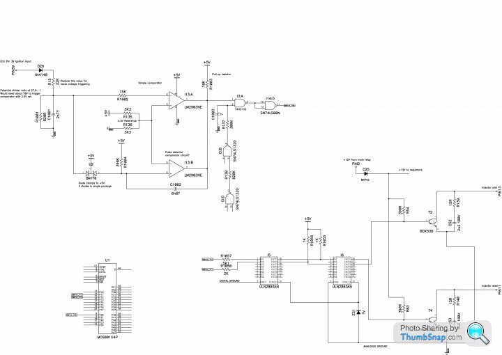
Neil, great work but there seems to be a discrepancy in the injector driver diagram, in Rover V8 14CUX variant:I've traced a bit further on the ignition input circuit, as well as the injector drive outputs for those interested, hope you can see the JPG OK. Beware it may not be 100% accurate!
6801U4_P11, MPU pin 14, is the out control line for the EVAP Purge Valve. Whereas 6801U4_P21, MPU pin 9, is the out control line for the Odd injector bank.
Here's how the Port 1 and Port 2 lines are set up in the Rover V8 14CUX variant:
Port 1 - P10 - Pin 13 - MIL Lamp
Port 1 - P11 - Pin 14 - Purge Valve
Port 1 - P12 - Pin 15 - Injector bank Even
Port 1 - P13 - Pin 16 - AC Condensor
Port 1 - P14 - Pin 17 - Stepper Motor Control line 1
Port 1 - P15 - Pin 18 - Stepper Motor Control line 2
Port 1 - P16 - Pin 19 - Fuel pump relay
Port 1 - P17 - Pin 20 - Main relay
Port 2 - P20 - Pin 8 - Ignition pulse from coil
Port 2 - P21 - Pin 9 - Injector bank Odd
Port 2 - P22 - Pin 10 - AC Compressor
Port 2 - P23 - Pin 11 - Receive Data, Comms interface
Port 2 - P24 - Pin 12 - Transmit Data, Comms interface
Interesting that 3-stages of Darlington Pair(s) are used, perhaps to meet the current demands of the injector coils?
Edited by davep on Friday 2nd July 15:22
davep said:
Neil, great work but there seems to be a discrepancy in the injector driver diagram, in Rover V8 14CUX variant:
Thanks, I see now that it's wrong after looking again. The port pinout helps a lot so I've traced out a good chunk more now, will update it soon here.davep said:
Interesting that 3-stages of Darlington Pair(s) are used, perhaps to meet the current demands of the injector coils?
I think the 3 stages are more for noise/EMC isolation than current amplification for the injector coils. The output Darlingtons are biased by those 390R pullup resistors which should give about 30mA of base drive, more than enough to saturate the transistor to allow max of about 10 amps for pulsed drive for the injectors. Will be interesting to see how much pulsed current they do draw.I think the two ULN2803 transistor arrays provide noise separation, as the I6 chip has the same ground as the output Darlingtons ('ECM ground' pin 14), but I5 has the same ground as the MPU ('Signal ground' ECU connector pin 27). Ultimately these connect together in the vehicle wiring harness, but keeping them apart on the PCB is good practice to prevent MPU latch up.
davep said:
Dan explained this 'dual functionality' some time back, the three Port 2 lines P20, P21, P22 during MPU RESET are used to define the Mode Select Logic. Once out of RESET the lines are used as data in/out lines, where P20 carries the ignition pulse edge of course. See page 31.
Thanks again, I went back and read page 31 and I see how that works now I've traced some more of the NAND logic circuit and corrected my mistakes. It appears to hold MPU P20 / pin 8 low for a few milliseconds after the MPU RESET pin is released high by the reset circuit, to ensure the correct MPU mode is selected after immediately reset.More soon as I get time.
Thank you Dave and CGCobra for the welcome back. Colin is doing fine. He's married now and living further away so I don't get to see him as often but he's not off-the-hook for any changes we may need to RG. He will be here tomorrow though because we will be celebrating my mother's 100th birthday. I hope she doesn't ask to drive the Griff.
Neil, I have a couple of points that you may want to keep in mind.
1) You may have noticed that the injector bank drive signals from the 6803 are opposite polarities. Pin 9 on the 6803 is active low while pin 15 is active high. So there should be an inverter stage in one of the circuits. I can't think of why they did it this way. Maybe you have some thoughts on this.
2) Generally, I'm impressed with the design and reliability of this ECU but there is one area where I'm not so sure. The drive circuit for the purge valve is a TO-92 package with no heat sink. This is T7 in the corner of the board near the power supply. On the two boards I tested, T7 appeared to be blown on both. Some boards have a 5 ohm power resistor (R141) in the output and other boards have a shorting wire in its place. LR may have had trouble with this circuit or maybe the change was the result of using a different purge solenoid on some vehicles. Either way, we are fortunate that in this particular case it makes no difference whether it works or not. I may have mentioned earlier in this thread that software seems to be attempting to drive the solenoid with pulses as short as 4 mSec. Maybe T7 gets stressed by the software.
danbourassa said:
Thank you Dave and CGCobra for the welcome back. Colin is doing fine. He's married now and living further away so I don't get to see him as often but he's not off-the-hook for any changes we may need to RG. He will be here tomorrow though because we will be celebrating my mother's 100th birthday. I hope she doesn't ask to drive the Griff.
Dan please convey my congratulations to Colin on his marriage and to your mother on becoming a centenarian. I hope you all enjoy your celebrations.danbourassa said:
Neil, I have a couple of points that you may want to keep in mind.
1) You may have noticed that the injector bank drive signals from the 6803 are opposite polarities. Pin 9 on the 6803 is active low while pin 15 is active high. So there should be an inverter stage in one of the circuits. I can't think of why they did it this way. Maybe you have some thoughts on this.
Thanks, I'd spotted this while fixing the incorrect first diagram, something else to think about why one is inverted! I also found out what option links K14 and K15 do, they route the injector signals to just MPU P21 output, or both P22 and P12 separately. These were some of the links I had to change to get the Austin 14CUX to work as a Rover 14CUX.1) You may have noticed that the injector bank drive signals from the 6803 are opposite polarities. Pin 9 on the 6803 is active low while pin 15 is active high. So there should be an inverter stage in one of the circuits. I can't think of why they did it this way. Maybe you have some thoughts on this.
danbourassa said:
2) Generally, I'm impressed with the design and reliability of this ECU but there is one area where I'm not so sure. The drive circuit for the purge valve is a TO-92 package with no heat sink. This is T7 in the corner of the board near the power supply. On the two boards I tested, T7 appeared to be blown on both. Some boards have a 5 ohm power resistor (R141) in the output and other boards have a shorting wire in its place. LR may have had trouble with this circuit or maybe the change was the result of using a different purge solenoid on some vehicles. Either way, we are fortunate that in this particular case it makes no difference whether it works or not. I may have mentioned earlier in this thread that software seems to be attempting to drive the solenoid with pulses as short as 4 mSec. Maybe T7 gets stressed by the software.
I'm not 100% sure what T7 actually is, I just assumed it looked like an NPN output so I've drawn it as that. It's marked S3643, but I don't know if that's a real part number or the Rover/Austin obfuscation number. It's much taller than a regular TO-92 transistor package though, so it could be a fairly beefy transistor. My PCB does have a 5R current limit resistor in series with T7, no idea if it works or not though, I have no purge valve to test it with.If you say the software attempts to modulate this output then it could well be that the solenoid current was overheating the drive circuit, or solenoid itself and causing failure. There is very little PCB copper to T7 pads, so very little in the way of heat removal even though there's plenty of empty PCB area around there. No heatsink and free air means it won't be able to carry much current for long periods.
Do you know much about the purge valve operation? Is it likely to be left energised for long periods of time? If so then it's an common method to pulse 100% at turn on then PWM it to reduce current and heat but keep enough current to hold the solenoid in place. Diesel fuel shutoff valves often work like this.
Updated injector drawing below, as usual likely to be mistakes and omissions, so beware! There's quite a lot missing around the regulator circuit.
Is there a better way for me to show diagrams here? I've been exporting PDF, then convert to JPG to upload on the forum, it's a bit messy to do, and will get less readable the larger the diagrams get. Does anyone host a 14CUX info website that could host a PDF of the diagrams perhaps? Or some other way?

davep said:
Re the injector driver circuit and the swapping of injector types. What differences, if any, do injector characteristics (inductance and reactance) make on the driver load circuit's current and voltage levels and injector coil operation, since some injectors are designed to work in parallel groups (1/LT = 1/L1+ 1/L2 ...) and some as single in series (LT = L1).
I've measured a single injector valve coil as 10mH inductance and 16 ohms resistance. They are wired 4 in parallel giving 4 ohms and a calculated 2.5mH total inductance. When I measured the bank together I got a reading of 312uH inductance, maybe I didn't hold the probes on very well. I'm fairly confident of the 10mH per injector though. The ones I have are standard Range Rover EFI 3.9 injectors as far as I know, they have a green band around the top.With 4 injectors in parallel, total drive current would be 3 amps (0.75A per injector), so well within the drive transistor specs of 8 amps.
At turn off I think it will take a few hundred microseconds (about 500uS) for the current to decay and the valve fully close. I don't know if this turn off time would be compensated for in the software?
At a guess I'd say you could drive more current safely from the 14CUX circuit, at the expense of more heat into the case. I wouldn't go much more than 5 amps total pulses though before risking driver damage.
Neil_Ward said:
Do you know much about the purge valve operation? Is it likely to be left energised for long periods of time? If so then it's an common method to pulse 100% at turn on then PWM it to reduce current and heat but keep enough current to hold the solenoid in place. Diesel fuel shutoff valves often work like this.
That's an interesting idea. I'd be surprised if the software was that sophisticated but I don't understand it well enough to say for sure.Neil_Ward said:
Is there a better way for me to show diagrams here? I've been exporting PDF, then convert to JPG to upload on the forum, it's a bit messy to do, and will get less readable the larger the diagrams get. Does anyone host a 14CUX info website that could host a PDF of the diagrams perhaps? Or some other way?
I find Google Drive to be convenient for sharing files.Here's how I think the ignition input circuit works. Please point out errors, omissions or my plain stupidity, I'm just trying to learn how this works.
The LM2903 dual comparator I13 on the diagram has open collector outputs, which means the output pins are either open circuit, or closed to 0V. This means that both outputs can be connected together so that only if both are open does a pullup reistor (R1003 on my diagram) allow the common output to go up to +5V. This is like a logical "OR" of both the outputs, if one or the other closes to 0V the common output goes to 0V. This method is used in the 14CUX ignition input circuit.
The heart of the input is comparator I13:A which will normally sit with its output closed to 0V if no ignition pulse is on ECU input pin 39. Comparator I13:B will normally have its output open at this point, as its -ve input pin is at a lower voltage (2.5V) than its +ve input pin (5V).
When an an ignition pulse voltage greater than about +70V is seen on ECU pin 39, this causes I13:A pin 2 to rise above 2.5V, triggering the output to open. This will allow R1003 to pull the output up to +5V, and feed into NAND gate I3:A pin 1.
At the same time as this voltage is rising to +5V, it pushes up the voltage across capacitor C1002 and would push I13:B pin 5 even higher than 5V unless it were clamped through one half of diode D1000. At this point I13:B output is still open circuit, so there is no change to the common output voltage.
Once the ECU pin 39 ignition input falls below its 70V threshold, the I13:A output turns on and closes to 0V. This also snaps capacitor C1002 to 0V and drags I13:B +ve input (pin 5) down to 0V too. This will turn on its output too, and keep the common output down at 0V regardless of what I13:A now output does. So it does not matter what ECU pin 39 does, it can spike back above 70V, but it will not now make the comparator common output rise again. This will remove any false ignition signals to the MPU.
It cannot remain locked out forever though, so while the common output is closed to 0V, capacitor C1002 will start to charge up to 5V via resistor R1004. Once I13:B pin 5 rises above 2.5V, its output will open and be ready for detecting another ignition input pulse. The time delay before the lockout is removed a is delay of about 2.5mS, from R1004 and C1002 time constant.
NAND gate I3:A takes two inputs, one is the ignition pulse common output from the comparators, the other is a delayed input from RC network R137 and C1003. After RESET goes high after power up, there will be a delay of a few mS before I3:A pin 2 goes above its Schmitt trigger level. This will force I3:A pin 3 output high for that period of time. This then feeds into gate I14 pins 12 and 13, and inverts the signal, so for that short reset delay MPU P20 pin 8 will be forced low. This is for the MPU mode select state.
After the reset delay, I3:A will now allow a high signal on pin 1 to change pin 3 low, and therefore MPU pin 8 high. This indicates an ignition pulse has been detected.

The LM2903 dual comparator I13 on the diagram has open collector outputs, which means the output pins are either open circuit, or closed to 0V. This means that both outputs can be connected together so that only if both are open does a pullup reistor (R1003 on my diagram) allow the common output to go up to +5V. This is like a logical "OR" of both the outputs, if one or the other closes to 0V the common output goes to 0V. This method is used in the 14CUX ignition input circuit.
The heart of the input is comparator I13:A which will normally sit with its output closed to 0V if no ignition pulse is on ECU input pin 39. Comparator I13:B will normally have its output open at this point, as its -ve input pin is at a lower voltage (2.5V) than its +ve input pin (5V).
When an an ignition pulse voltage greater than about +70V is seen on ECU pin 39, this causes I13:A pin 2 to rise above 2.5V, triggering the output to open. This will allow R1003 to pull the output up to +5V, and feed into NAND gate I3:A pin 1.
At the same time as this voltage is rising to +5V, it pushes up the voltage across capacitor C1002 and would push I13:B pin 5 even higher than 5V unless it were clamped through one half of diode D1000. At this point I13:B output is still open circuit, so there is no change to the common output voltage.
Once the ECU pin 39 ignition input falls below its 70V threshold, the I13:A output turns on and closes to 0V. This also snaps capacitor C1002 to 0V and drags I13:B +ve input (pin 5) down to 0V too. This will turn on its output too, and keep the common output down at 0V regardless of what I13:A now output does. So it does not matter what ECU pin 39 does, it can spike back above 70V, but it will not now make the comparator common output rise again. This will remove any false ignition signals to the MPU.
It cannot remain locked out forever though, so while the common output is closed to 0V, capacitor C1002 will start to charge up to 5V via resistor R1004. Once I13:B pin 5 rises above 2.5V, its output will open and be ready for detecting another ignition input pulse. The time delay before the lockout is removed a is delay of about 2.5mS, from R1004 and C1002 time constant.
NAND gate I3:A takes two inputs, one is the ignition pulse common output from the comparators, the other is a delayed input from RC network R137 and C1003. After RESET goes high after power up, there will be a delay of a few mS before I3:A pin 2 goes above its Schmitt trigger level. This will force I3:A pin 3 output high for that period of time. This then feeds into gate I14
pins 12 and 13, and inverts the signal, so for that short reset delay MPU P20 pin 8 will be forced low. This is for the MPU mode select state.After the reset delay, I3:A will now allow a high signal on pin 1 to change pin 3 low, and therefore MPU pin 8 high. This indicates an ignition pulse has been detected.
danbourassa said:
1) You may have noticed that the injector bank drive signals from the 6803 are opposite polarities. Pin 9 on the 6803 is active low while pin 15 is active high. So there should be an inverter stage in one of the circuits. I can't think of why they did it this way. Maybe you have some thoughts on this.
After looking back at page 31 of this thread about the MPU mode select (thanks to davep), I see that the 6801U4 datasheet states that there are three pins used for the mode select on start up. One of these pins is pin 9, port P21 that is also used as one of the injector drive output compare signals.At start up, just after reset, this pin will be an input which is desired to be pulled high by resistor R1060 on my diagram. This needs to be high for the mode select, but it would be a bad idea that when this pin is pulled high, it would be firing the injector drive circuit too.
By inverting the signal through inverter gate I15: D, the port P21 can be high after reset as desired, but not turning on the injector drive via I5 and I6, etc. at the same time.
I guess the software is set up to initialise P21 as an active low output compare, whereas P12 can remain active high output compare and save the cost/space of another inverter.
danbourassa said:
I find Google Drive to be convenient for sharing files.
Thanks for that suggestion, I hope this link will work then. I've put PDF versions of the schematics on this shared drive:https://drive.google.com/drive/folders/1IIPwsbVtUP...
Hopefully that will be easier and clearer to view, and I can update with the inevitable changes.
Neil_Ward said:
Thanks for that suggestion, I hope this link will work then. I've put PDF versions of the schematics on this shared drive:
https://drive.google.com/drive/folders/1IIPwsbVtUP...
Hopefully that will be easier and clearer to view, and I can update with the inevitable changes.
Nice work, it's coming together really well.https://drive.google.com/drive/folders/1IIPwsbVtUP...
Hopefully that will be easier and clearer to view, and I can update with the inevitable changes.
Some small changes for you:
Standby RAM Voltage
Pin 5 on the MPU standby voltage should be Pin 15, and the output is to 6801U4_P21. The +12 V supply for Pin 15 is permanent (assuming a battery is fitted), being directly fed from the battery, not via the ignition switch circuit.
Fuel Pump relay O/P circuit
On a Rover V8 variant this should be via connector Pin 16. If the PCB circuit is wired for Pin 12, then the Initialisation code for Port 1 needs to be re-checked. Land Rover did swap the Main and Fuel Pump relay circuits around in earlier variants.
Similarly, the Main Relay is energised via Pin 12, not Pin 16.
AC Condensor
Pin 36 is the feed for a relay/timer.
Don't want to come across as a nit-picker, but this work is so good it deserves to be correct.
Neil_Ward said:
I've measured a single injector valve coil as 10mH inductance and 16 ohms resistance. They are wired 4 in parallel giving 4 ohms and a calculated 2.5mH total inductance. When I measured the bank together I got a reading of 312uH inductance, maybe I didn't hold the probes on very well. I'm fairly confident of the 10mH per injector though. The ones I have are standard Range Rover EFI 3.9 injectors as far as I know, they have a green band around the top.
With 4 injectors in parallel, total drive current would be 3 amps (0.75A per injector), so well within the drive transistor specs of 8 amps.
At turn off I think it will take a few hundred microseconds (about 500uS) for the current to decay and the valve fully close. I don't know if this turn off time would be compensated for in the software?
At a guess I'd say you could drive more current safely from the 14CUX circuit, at the expense of more heat into the case. I wouldn't go much more than 5 amps total pulses though before risking driver damage.
Thanks for doing this Neil. You probably have the OEM Lucas ERR 722 injectors. Your readings and values seem to tie in nicely with this diagram: With 4 injectors in parallel, total drive current would be 3 amps (0.75A per injector), so well within the drive transistor specs of 8 amps.
At turn off I think it will take a few hundred microseconds (about 500uS) for the current to decay and the valve fully close. I don't know if this turn off time would be compensated for in the software?
At a guess I'd say you could drive more current safely from the 14CUX circuit, at the expense of more heat into the case. I wouldn't go much more than 5 amps total pulses though before risking driver damage.
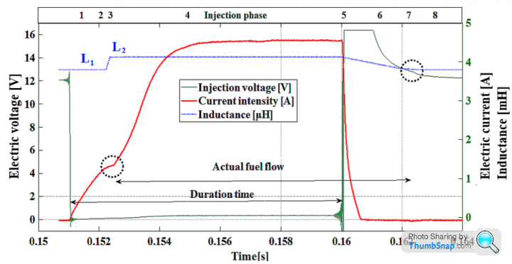
Courtesy of: Krzysztof Więcławski, Faculty of Automotive and Construction Machinery Engineering, Warsaw University of Technology, 02-524 Warsaw, Poland
There's a fair bit to absorb here, so I'll get back to you later.
Edited by davep on Monday 5th July 11:32
davep said:
Fuel Pump relay O/P circuit
On a Rover V8 variant this should be via connector Pin 16. If the PCB circuit is wired for Pin 12, then the Initialisation code for Port 1 needs to be re-checked. Land Rover did swap the Main and Fuel Pump relay circuits around in earlier variants.
Similarly, the Main Relay is energised via Pin 12, not Pin 16.
Thanks again Dave, all interesting stuff. I've traced a bit more of the main relay circuit and there's more to it than just another signal from the micro port, though it's getting quite challenging to trace out now, as it goes into a fair bit of the surface mount components on the underside. I've updated my typo on pin 15,changed some text and fixed a few more part numbers too.On a Rover V8 variant this should be via connector Pin 16. If the PCB circuit is wired for Pin 12, then the Initialisation code for Port 1 needs to be re-checked. Land Rover did swap the Main and Fuel Pump relay circuits around in earlier variants.
Similarly, the Main Relay is energised via Pin 12, not Pin 16.
Probably a long shot, but if anyone here has a dead/damaged 14CUX PCB that they'd consider selling me for a reasonable cost then I'd be interested. It's getting difficult to trace out some parts of the PCB now, and it would be easier to de-solder parts to measure them and follow PCB tracks more quickly. I don't want to risk damage to a good working one though, mine or anyone else's. The conformal coating makes it difficult too, so I'd look to strip that off to make continuity checking easier.
davep said:
Don't want to come across as a nit-picker, but this work is so good it deserves to be correct.
Absolutely do keep pointing out the typos and mistakes, it's great to have someone looking and checking as I go for a change. Only that way can it be correct and we can hopefully all learn more.That injector current graph is very interesting, particularly around the left dotted circle where fuel delivery starts. It shows a change in the slope of the coil current rise, I guess as the spool valve lifts off its seal and pulls into the coil, thereby changing the overall inductance. I've never considered that the coil inductance would change as the metal moves into the coil core on a valve, but it would change now I think about it, so thanks again for the information.
Neil_Ward said:
That injector current graph is very interesting, particularly around the left dotted circle where fuel delivery starts. It shows a change in the slope of the coil current rise, I guess as the spool valve lifts off its seal and pulls into the coil, thereby changing the overall inductance. I've never considered that the coil inductance would change as the metal moves into the coil core on a valve, but it would change now I think about it, so thanks again for the information.
If you are interested there's a lot of detailed information here:https://www.mdpi.com/1424-8220/20/15/4151/htm
Interesting that you picked up on the circle around the 'stage 2 nozzle opening' as this is where injector experts will talk about the characteristic of injector dampening; especially under- and over- in the early stages of the fuel flow curve. I think when changing injectors from the original Lucas to another type, for example a type designed to work as a single in series inductive load circuit, i.e. sequential FI so fired once/720°, this dampening characteristic may have an impact on overfuelling (under-dampening).
Brilliant Work Neil, CG Cobra and Dave plus great to see Dan back on top form, sorry I can’t contribute with the hardware but certainly a helpful & interesting read.
Mark Adams installs the Omex ignition only ECUs with the 14CUX and I assumed he uses the Tachometer output to trigger the 14CUX but I don’t actually know, can anyone confirm. CG Cobra, does your ignition ECU have a Tachometer output?
I'm currently interested in how the introduction of the leaner E10 fuel in the UK in September will effect the running of our 14CUX vehicles. We all know the 14CUX narrowband lambda sensors only reads richer or leaner than stoichiometric but will the stoichiometric point shift with the leaner E10 fuel so the code automatically injects more fuel? Also what about above 3,400rpm & will non-cat cars running open loop need the main scalar increasing or is the difference so negligible it shouldn’t cause any issues?
To get the best of both fuels would non-cat cars require 2 maps? Any excuse to run dual maps.
Also, if I don’t switch to mapping with Lamba how much richer should the following target AFR be for E10 fuel?
11.5 Best Rich Torque at Wide Open Throttle (WOT)
12.0 Fast opening throttle & Accelerating
12.2->12.5 WOT Best safe Power/Acceration 2000-> 4500
12.5->13 WOT Best Performance 3000 -> 6000
13.5 Best non-cat open loop idle
14.7 Stoichimometic least Pollutants
15.5 Lean Cruise but not the very best for the environment
15.5-16.5 Best Economy
The place you need to start I'd with your AFR readings on the two different fuels and open loop and see if there is any perceptible shift in readings. Dont forget the AFR is based on excess oxygen, so the question really is does the chemistry of the burn change enough to be detected?
spitfire4v8 said:
The weakening effect of 10 percent ethanol is less than 3 percent on the mixture strength. Unless you have a car already running on the weak side of safe you won't notice a difference.
Anything under lambda control will automatically richen up.
Thanks for your reply, is that 3% less from the current E5 or gasoline?Anything under lambda control will automatically richen up.
I’ve read/heard stoichiometric for E10 is 14.1 oppose to gasoline 14.7, therefore on full load I’ve been aiming for low 12s instead of high 12s & hope the following AFRs will also be ok with E10.
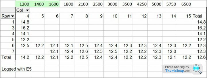
Joolz, you can see I'm running your suggested rpm columns
Hi Folks,
Not been around for a while but good to see the thread is alive and well!
AFM question, does anyone know where I can source a decent 5AM for my 3.5? Got a whole load of them spare and all cause misfiring under load to varying degrees (disconnect and the problem goes and performance is restored!). Failing that is anyone able to modify my map to accept a GEMS or 20AM AFM?
Cheers
Steve
Steve
Might be worth contacting spitfire4v8 (Joolz) as he removes 5AM when installing after market ECUs, I’m sure you know all 5AMs are the same regardless of engine size.
Unfortunately a 3.5 will not flow enough air to use a GEMs 20AM, alternatively to future proof your Rangie you could try the later Bosch 4.0L Land Rover Discovery 2 MAF (AFM) 0 280 217 532 / ERR7171G but would require a step down hose adapter & a full re-map which Joolz could do for you.
I've been running a Bosch MAF 4.6L for the last 3 years and has proved 100% reliable and more consistent with varying engine bay temperatures because the electronics are inside the cool air stream.
Gassing Station | Griffith | Top of Page | What's New | My Stuff