Instructions to change fuel maps on 14CUX Griffith, Chimaera
Discussion


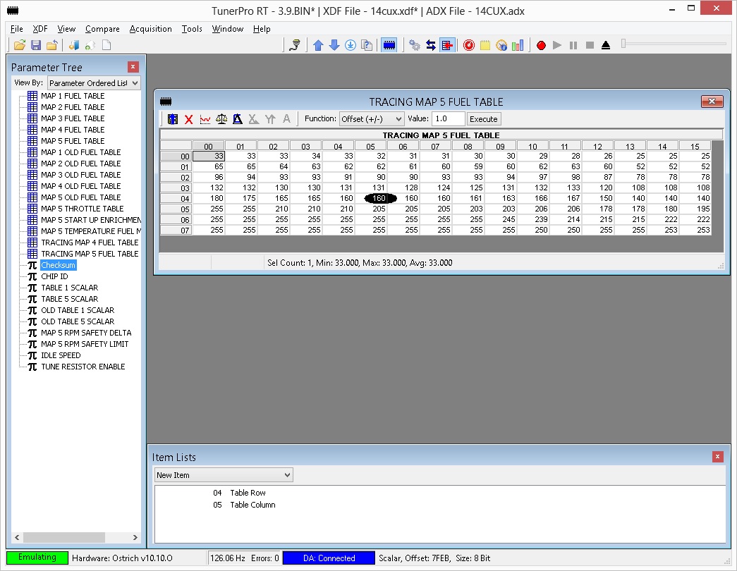
This evening I worked on a custom ADX to allow data tracing within tunerpro. I'll edit with the link once I zip it all up.
edit: link is http://www.flemcodesign.com/files/14CUX_CHECKSUM2....
the floating oval shows the current cell that is use per Collin and Dan's documentation.
Mark @ Tunerpro sounds pretty enthusiastic about the project and has agreed to host the files. You can now find the definition files on his site. I'm going to play with the cell tracing some this weekend before sending him the updated files and adx file.
It uses the same cable as RoverGauge, select the ADX file and configure it for your com port and go! I'll add more gauges as I find them necessary for tuning. I don't want to step on anyones toes and RoverGauge is a fine enough diagnostic tool that there is no need to duplicate all of its functions in tunerpro.
Edited by robertf03 on Saturday 21st September 05:05
Edited by robertf03 on Saturday 21st September 05:06
On the issue of how to calibrate with lambda feedback, you can fool the ECU to zero trim with the correct signal. I initially thought that if you fed an perfect 1 volt square wave into the Lambda probe input of the ECU it would simply zero the trim, but not quite, it needs tweaking a bit. You have to alter the mark space ratio (the high or low time for the fake lambda signal) whilst watching the short term trim with RoverGauge (Or ECUmate will do do) until the trim cycles as near the zero point as you can get it. You then reset the ECU to zero the long term trim, and the mixture now only cycles fractionally around the mid point with the fake signal, so no significant trim is added. You could then alter the map to the point the now disconnected lambda output probes switches for absolute minimum trim once its reconnected. I dont see how you can map properly without doing this, but Ive never heard anyone mention anything like this during a mapping session?? Ill try and post some readout displays tomorrow if I get a bit more road time.
blitzracing said:
On the issue of how to calibrate with lambda feedback, you can fool the ECU to zero trim with the correct signal. .
That's what I suggested earlier in this thread. But there must be a way of doing it inside the code as well. Also has lowering the coolant temperature been tried/discussed - as I assume it wont go closed loop until the engine is up to temp. I assume the CLT is used for warmup enrichment as well, but you may be able to fake it at a high enough temperature to achieve what you need.
eliot said:
That's what I suggested earlier in this thread. But there must be a way of doing it inside the code as well. Also has lowering the coolant temperature been tried/discussed - as I assume it wont go closed loop until the engine is up to temp. I assume the CLT is used for warmup enrichment as well, but you may be able to fake it at a high enough temperature to achieve what you need.
If that can be implemented within the code that would be a good idea IMO 
eliot said:
That's what I suggested earlier in this thread. But there must be a way of doing it inside the code as well. Also has lowering the coolant temperature been tried/discussed - as I assume it wont go closed loop until the engine is up to temp. I assume the CLT is used for warmup enrichment as well, but you may be able to fake it at a high enough temperature to achieve what you need.
It goes into closed loop as soon as the lambda probes get hot- typically around 25 seconds on a cold engine. On the whole issue of running a richer mixture on cold start as I understand it, is not all the fuel reaches the combustion chamber as it condenses on the inlet tract, so the mixture simple becomes too lean, so you have to add extra. The level of excess oxygen in the exhaust will still still reflect the correct burn even on a stone cold engine, so you can still use the feedback from the probe.In terms of code- maybe simply resetting the long term trim on say a 10 second basis to prevent it being set in the first place as its in RAM (?). You then map on the probe switching point. Extra hardware is a messy way of going about it, but it does work if all else fails.
Not sure if you got my point. Trick the engine into thinking its not fully warmed up by replacing the clt sensor with a pot. You then adjust the pot to find the point where closed loop activates, and adjust back down slightly. The reason you dont want to make it stone cold, is because as we know it will be enriching the mixture because it thinks it's cold.
I'm sure you could find the closed loop / clt point by code disassembly too, but a pot is quick and easy!
These are only suggestions based on my knowledge of other ECU's - i.e i know they wont go closed loop until the engine is up to a certain temp.
I'm sure you could find the closed loop / clt point by code disassembly too, but a pot is quick and easy!
These are only suggestions based on my knowledge of other ECU's - i.e i know they wont go closed loop until the engine is up to a certain temp.

blitzracing said:
It goes into closed loop as soon as the lambda probes get hot- typically around 25 seconds on a cold engine. On the whole issue of running a richer mixture on cold start as I understand it, is not all the fuel reaches the combustion chamber as it condenses on the inlet tract, so the mixture simple becomes too lean, so you have to add extra. The level of excess oxygen in the exhaust will still still reflect the correct burn even on a stone cold engine, so you can still use the feedback from the probe.
In terms of code- maybe simply resetting the long term trim on say a 10 second basis to prevent it being set in the first place as its in RAM (?). You then map on the probe switching point. Extra hardware is a messy way of going about it, but it does work if all else fails.
Hi Mark In terms of code- maybe simply resetting the long term trim on say a 10 second basis to prevent it being set in the first place as its in RAM (?). You then map on the probe switching point. Extra hardware is a messy way of going about it, but it does work if all else fails.
 so are you saying that the CUX does not reach a temp threshold i.e 65/70 approx degrees before going onto CL ?
 Dan/Colin
As Mark has lambdas probes with no cats is their any point him copying map 5 to map 2 to turn the lambdas off to see if the results are similar. I’m thinking it could be a way to temporary run in open loop while tuning or is their different tables like the start up enrichment, throttle and temperature for each map.
I’ll have to fit some lambdas probes this winter so I can help with the testing.
Steve
Robert
You’ve made great progress with Tunerpro and added extra tables, scalars and checksum.dll. I can confirm TunerPro is now updating both images but checksum.dll only corrects both images the first time round. On the second save it only corrects 7FEB and doesn’t make any difference if you are emulating or not. Sorry busy weekend but I hope to get out and play with data tracing this week.
Cheers Steve

eliot said:
I think we are both suggesting the same thing 
Being a sad muppet I measured the lambda probe response from cold, and as soon as the probe output goes high (rich mixture engine stone cold) the CPU starts to cycle the mixture in closed loop, long before the engine has warmed up. You can hear it on a cold engine, the idle note changes as it backs the fuel off after a very rich starting point.robertf03 said:
Dan, do you know what RAM address the heated winshield voltage is stored at?
I'd like to run the 5 volt out from my wideband in to the windshield input so I can datalog all with one program
Robert, unfortunately, it's not stored. The incoming voltage is 8-bit converted and bit 7 is tested. The result is that a bit in memory is set or cleared to indicate the state of the heater. It seems a waste to use a channel capable of 10-bit A to D to just resolve a logic state, but that's done for several of the ADC channels.I'd like to run the 5 volt out from my wideband in to the windshield input so I can datalog all with one program
It would take very little code at the PROM end of things to make the change you want. I assume you just want to store the 8-bit value in an unused RAM location. If you want, I could help you with this change.
danbourassa said:
It would take very little code at the PROM end of things to make the change you want. I assume you just want to store the 8-bit value in an unused RAM location. If you want, I could help you with this change.
Dan and Robert, you two never cease to amaze me and now you are considering code changes; I never would of believed it. Will you compile your reversed engineered assembly code or edit the executable code in hex? Robert, it’s a really neat idea what you are planning to do and I really hope you get it to work. Humm, when (not if) you crack it I may have to copy you and buy the same gas analyser if you don’t mind.All the best, Steve
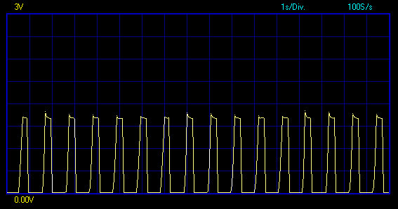
Spent a bit more time on fooling the ECU lambda readings. The origional circuit Id used with a 555 timer changed the overall frequency of the waveform as you changed the mark space ratio. Id assumed that the faster the lambda signal changed frequency wise the better, but I think the ECUs lambda monitoring is pretty slow and throwing a high frequency switch rate simply confuses it poor little brain. Back to the drawing board with some very basic electronics in the form of a transistor multivibrator. The ECU seems to respond well to a switch rate of about 2 hz and no more, so the rest was simply a case of altering the high or low times within that 2 HZ window to fake a rich or lean signal. Having got it working and plugged in it became apparent that a fractional shift in the wave form would be enough to make the ECU start to add long term trim, that you dont want when mapping. The problem is, the ECU adds a bit of long term trim to compensate for the "wrong signal", but it still gets the same signal back as its a fake, so it adds a bit more trim, and on it goes until it hits the max long term trim. This means the test signal must be very accurate with an equal rich / lean cycle. The voltage is pretty critical too as an over high voltage is picked up as a longer rich period, and like wise a low voltage as lean. So here is the results. This is an enforced real world lean condition with the ECU then compensating. Note the long periods of 0 volts, and the spikey waveform:
Gassing Station | Griffith | Top of Page | What's New | My Stuff