Simple questions for a newb to Cerbera DIY
Discussion


Salutations all,
Up until now I've paid (sorry PAID because it needed a full body off chassis reconditioning despite the TVR dealer who inspected it saying it was OK) for all the work to be done to my Cerbera 4.5. So out of the 18 months ownership I've only seen her for 11 :-(
Now I finally have a double garage and so starts the fixing the oil leak I still have post the re-chassis.
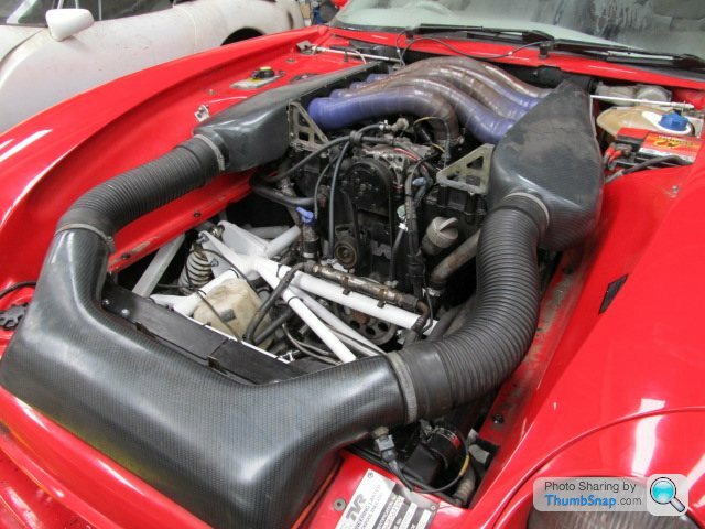
To do this I need to remove the panel under the bonnet (the one you top the screen wash up through) held down by the 6 bolts. Bolts are easy but then how does one extract the panel? I'm sure it is simples but I can't figure it out.
I've had some rather interesting electrical issues, door opening issues and a bunch of other stuff which I'll try and post as we go. Last one was a magic box under the dash called and "Intelligent Speedometer" or something (I think made by Steve Heath as a kit in the past) converting from the old variable reluctance sensor to a 'digital' on-off type sensor. Electronics being what I studied don't you know I've got that one fixed. Full details once I'm sure I understand it correctly.
More soon but if someone can tell me the bleedin' obvious I'd be most grateful.
boomshanka
Wurgle
Up until now I've paid (sorry PAID because it needed a full body off chassis reconditioning despite the TVR dealer who inspected it saying it was OK) for all the work to be done to my Cerbera 4.5. So out of the 18 months ownership I've only seen her for 11 :-(
Now I finally have a double garage and so starts the fixing the oil leak I still have post the re-chassis.
To do this I need to remove the panel under the bonnet (the one you top the screen wash up through) held down by the 6 bolts. Bolts are easy but then how does one extract the panel? I'm sure it is simples but I can't figure it out.
I've had some rather interesting electrical issues, door opening issues and a bunch of other stuff which I'll try and post as we go. Last one was a magic box under the dash called and "Intelligent Speedometer" or something (I think made by Steve Heath as a kit in the past) converting from the old variable reluctance sensor to a 'digital' on-off type sensor. Electronics being what I studied don't you know I've got that one fixed. Full details once I'm sure I understand it correctly.
More soon but if someone can tell me the bleedin' obvious I'd be most grateful.
boomshanka
Wurgle
Hello all
Thanks for all the quick replies. I guess its the F1 panel.
I had wondered if it were possible to remove without air filter box etc. because I have a photo of the car during its rebuild showing it all in without this panel.
Mine is a 1998 model so I don't know if that is early or late in this context?
Location wise I'm about a mile from Neil Garner.
Doors are all working fine now thankfully although the boot catch height needs a minor adjustment I think.
In case it is useful for anyone else...
Drivers Door Will Not Open
Note that for this repair most of the work was done by my father so the use of the pronoun “I” should really read “The Dodo” in most cases.
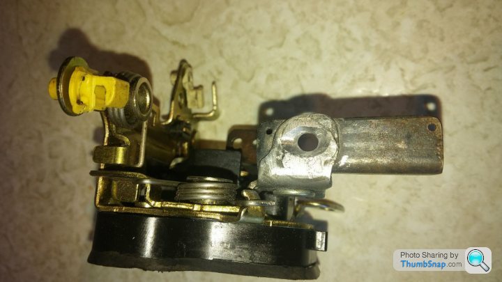
The door solenoids were replaced just before I picked up the car because sometimes it took more than one push of the button to open the door. For those unfamiliar this is not actually a solenoid but some sort of motor that drives the white plunger which has a rack on it. The spring on the door mechanism is what returns it.
Here you can see that the rubber boot has been removed. This is because the way it was faulty, described in a minute, had caused the white rod to become slightly bent and it needed some very careful bending back.
I also used this opportunity to squirt some silicon oil into the inside of the actuator to help it smoothly run after its ordeal. Overall success I hope.
This one has blue and green wires. The green is 0V and the blue +12V. This is also indicated by the +12V on the black plastic case.
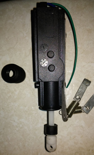
Point to note here is the shape of the end of the actuator rod and the hole in it. This, when correctly fitted, goes through a slot in the door mechanism. A pin goes through the hole allowing it to act as an axle when it pushes.
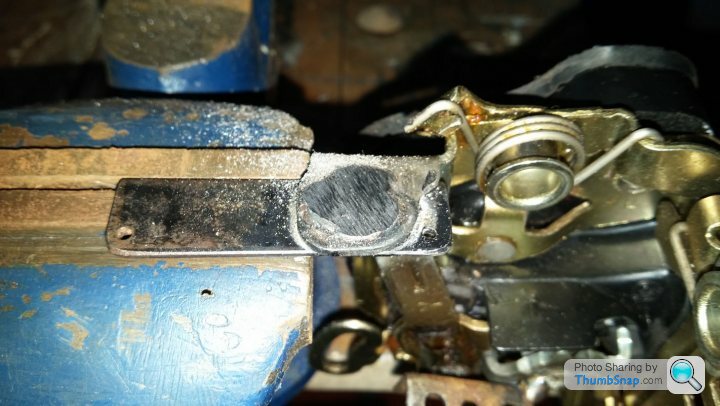
After extracting the door mechanism I discovered that there had for some inexplicable reason been a lump of metal welded to the mechanism where the actuator should poke through and there was no sign of a axle-pin.
Here you can see I am just starting to file the weld splat off.
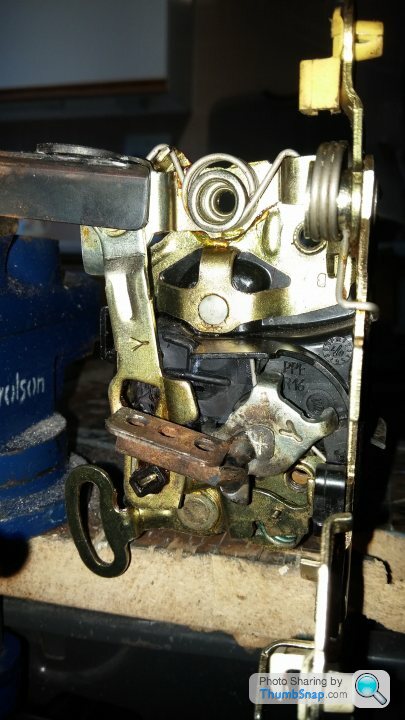
A side on shot of the mechanism shows the issue. The actuator will push down on the black metal bit causing it to be at an angle to the actuator base which promptly tries to skid off the plate sideways bending the actuator rod and meaning the two springs in the door mechanism have not got the power to return the actuator.
Note that there are two springs as this part was designed to work on a normal key car. The mechanism can be deadlocked and in this position only one spring will try and return the actuator rod which it is not generally strong enough to do. Also it won't open the door. So check you have it right before replacement as it will be much easier to sort out when not inside a car. I'm not sure if it is correct in this photo but adjustment of the blackish bit that looks like a old key handle (bottom left) and the rusty bit above-right of it should sort you if you somehow deadlock the door.
To fix mine I made a small rounded hole in where the weld spot is to locate the actuator rod and stop it slipping out as per a crude socket of a ball-and-socket.
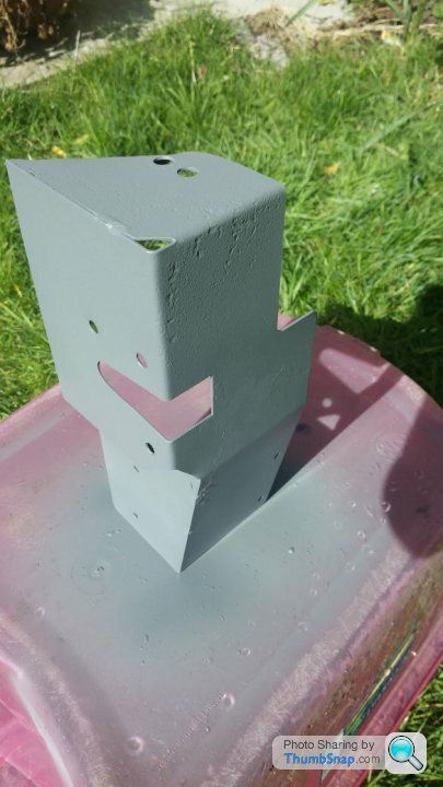
In this process it is worth taking the body-side of the door lock out and sorting all the rust and then zinc primer etc.
And lastly when I came to it the replacement actuators were not fitted very well electrically so I opted to solder and heatshrink them.
Thanks for all the quick replies. I guess its the F1 panel.
I had wondered if it were possible to remove without air filter box etc. because I have a photo of the car during its rebuild showing it all in without this panel.
Mine is a 1998 model so I don't know if that is early or late in this context?
Location wise I'm about a mile from Neil Garner.
Doors are all working fine now thankfully although the boot catch height needs a minor adjustment I think.
In case it is useful for anyone else...
Drivers Door Will Not Open
================
Note that for this repair most of the work was done by my father so the use of the pronoun “I” should really read “The Dodo” in most cases.
The door solenoids were replaced just before I picked up the car because sometimes it took more than one push of the button to open the door. For those unfamiliar this is not actually a solenoid but some sort of motor that drives the white plunger which has a rack on it. The spring on the door mechanism is what returns it.
Here you can see that the rubber boot has been removed. This is because the way it was faulty, described in a minute, had caused the white rod to become slightly bent and it needed some very careful bending back.
I also used this opportunity to squirt some silicon oil into the inside of the actuator to help it smoothly run after its ordeal. Overall success I hope.
This one has blue and green wires. The green is 0V and the blue +12V. This is also indicated by the +12V on the black plastic case.
Point to note here is the shape of the end of the actuator rod and the hole in it. This, when correctly fitted, goes through a slot in the door mechanism. A pin goes through the hole allowing it to act as an axle when it pushes.
After extracting the door mechanism I discovered that there had for some inexplicable reason been a lump of metal welded to the mechanism where the actuator should poke through and there was no sign of a axle-pin.
Here you can see I am just starting to file the weld splat off.
A side on shot of the mechanism shows the issue. The actuator will push down on the black metal bit causing it to be at an angle to the actuator base which promptly tries to skid off the plate sideways bending the actuator rod and meaning the two springs in the door mechanism have not got the power to return the actuator.
Note that there are two springs as this part was designed to work on a normal key car. The mechanism can be deadlocked and in this position only one spring will try and return the actuator rod which it is not generally strong enough to do. Also it won't open the door. So check you have it right before replacement as it will be much easier to sort out when not inside a car. I'm not sure if it is correct in this photo but adjustment of the blackish bit that looks like a old key handle (bottom left) and the rusty bit above-right of it should sort you if you somehow deadlock the door.
To fix mine I made a small rounded hole in where the weld spot is to locate the actuator rod and stop it slipping out as per a crude socket of a ball-and-socket.
In this process it is worth taking the body-side of the door lock out and sorting all the rust and then zinc primer etc.
And lastly when I came to it the replacement actuators were not fitted very well electrically so I opted to solder and heatshrink them.
Fixing the speedometer
My car turns out to have the Steve Heath “Intelegent Speedo” box fitted and as Mr. Heath seems to have vanished I guessed it was up to me to reverse engineer and fix it.
I found http://www.shengltd.com/tvrextras/docs/Speedo%20Se...
which describes the unit. This is my understanding so far. As it turned out to be a dodgy connector I've not needed to get the oscilloscope out so I'm not 100% on all this.
Fault finding
In the test position 70mph was displayed on the speedo indicating that the speedometer itself and the wiring North of the box was OK. However if you read the pdf there is a suggestion that the wires can be crimped into the pins with pliers if you don't have the crimp tool. IMHO bad news and on examination many of mine were loose. This was not the fault though.
To find the fault I tested from the yellow wire at the point of the connector and the black wire to where the sensor plugs in. Continuity on the black (ground) but not the grey (what the yellow wire turns into). I then discovered it had continuity from the loom connector near the differential forward to the instruments connector and from the loom connector near the differential back to the actual sensor but not when this loom connector was mated from the instruments connector to the sensor ergo this loom connector was broken. Fixed :-)
Reverse engineering
It seems this unit has the variable reluctance sensor used by TVR replaced with another 2 wire digital sensor that goes closed-circuit when a tooth goes by. You therefore get a number of pulses per second related to the speed. However these pulses are more frequent but shorter as the wheel speeds up so the energy sent to the speedometer does not go up in the same way as with the VR sensor where the energy goes up as the wheel speeds up. I'm a bit shaky on the exact functioning of VR sensors but the digital one is simple enough to understand. Therefore with the new digital sensor you need to convert the pulses from variable length to fixed length so as the speed goes up the mark-space of the pulse train goes up and the average voltage of the pulse train supplied to the speedometer goes up. A basic frequency to voltage converter.
Now for the interesting bit.
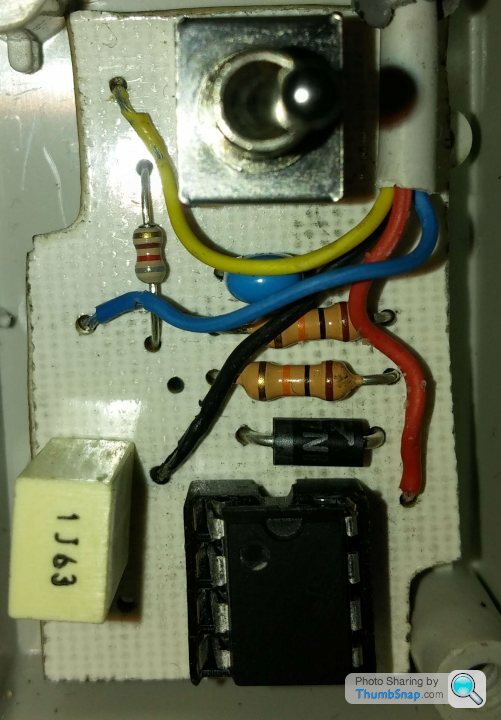
I may yet be proved wrong but the 'magic' speedo box in the car looks to me like a NE555 timer rather than a microprocessor. On mine I notice the IC markings have been sanded off so I can't say for sure but:
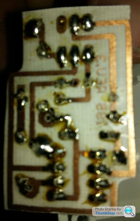
Looking at the tracks (I've flipped the copper side photo to make tracing easier)
Pins 4 and pin 8 connected are connected to +Volts
Pin 1 connected to ground
Pin 2 & 6 connected
Pin 5 floating (should be connected to ground with a 100nF capacitor unless your doing something rather clever but if your shaving cents off the price and can get away with it...)
Pin 3 output
All looks rather like a NE555 although it does not seem to be a standard mono-stable circuit.
I have a slight worry here as the resistors have a gold band i.e. 5% and the timing capacitor won't be any better so there is scope for it being quite inaccurate.
Aside: Also the chip socket is a sprung socket rather than a turned pin. Difference is about 20p and about 10000% reliability.
These days you could get 1% components and so it could be rather better but it's still not how I would do it. There are frequency to voltage converter chips available such as the LM2907 / LM2917 which should work but the issue with these is while the linearity is more than good enough they suffer from the fact that the F-->V ratio is still determined by analogue capacitors and resistors. It should still be possible to do though using a multi-turn trimmer and choosing capacitor dielectric that is accurate stable with things like temperature.
These days what might be a better way is to use something off the shelf like an Arduino Nano which could count the pulses using a quartz crystal for timing and output a PWM voltage. This was my initial guess for how this box would be working until I started digging.
If anyone out there knows anything about this box of tricks or has any corrections to the above do let me know.
I could revert to standard but as it works now :-) Also the bracket is different and a new sensor is £50. I understood that the original is also a common failure as the VR sensor has to run very close to the cog so gets damaged by flying muck. Just really posted the speedo stuff in case anyone else had gremlins in this department. I'll be asking more daft questions once i get the panel off i expect.
Gassing Station | Cerbera | Top of Page | What's New | My Stuff